 Find a Hobby Shop
 Live Chat
Posted: 12/25/20
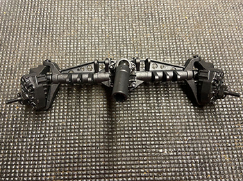
The Ultimate Four-Wheel Steering RC Crawler mod for the Axial Capra.
Looking to make arguably one of the most important, useful, and fun upgrades to your 1/10th scale Axial Capra? Look no further than the four-wheel steering mod (or 4WS). In this article, we will cover what parts, electronics, and setup you need to equip either your 1/10 Capra 1.9 Unlimited 4WD Trail Buggy Brushed RTR or 1/10 Capra 1.9 4WD Unlimited Trail Buggy Kit with this modification.
First off, let’s talk parts. Fortunately, mechanical work is the “easy part” of this whole modification. We are essentially removing the entire rear-end axle and portal housings. Then, we will be “duplicating” the entire front-end in place of what we removed. As a result, you will need to order quite a few parts to accomplish the physical swap. But, don’t let this discourage you as the actual “job” is quite simple. Please reference the list of parts at the bottom of this article. This will provide you everything necessary to integrate four-wheel steering on your Capra Trail Buggy.
Getting your electronics set up properly and functioning as you desire is where this gets tricky. In order to use traditional steering, throttle/brake, DIG, and four-wheel steering, you will need a 4-channel receiver (minimum). If you do NOT have an available AUX port on your receiver, you will either need to upgrade your receiver OR read over the disclaimer directly below this as it is applicable to this situation as well.
Important note for RTR Capra Owners and/or 3-channel receiver-limited rigs: If you intend on using the stock radio/receiver that is installed in your RTR Capra, you absolutely MUST purchase a “reversing Y-harness adapter.” Additionally, you will NOT be able to dynamically turn off/on four-wheel steering and/or use “crab” functionality (this will be discussed later in the article). Swapping to 4WS via this method will require permanent 4WS operation. Finally, you will not be able to adjust the trim of the front/rear axle independently.
Still with me? Let’s begin!
Physical Modification
Step 1:
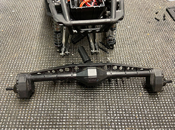
Remove all four wheels and tires from your Capra. Then, remove the rear axle housing from the chassis (believe it or not, it’s only held on by four screws). This is also a good opportunity to remove the lid from the mock fuel cell that houses your receiver. We will need access to this later.
Step 2:
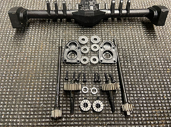
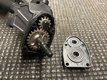
Move your Capra off to the side of your bench as all focus will be on the axles for the time being. Remove each wheel hex and the spacer directly behind them. Remove the four screws that hold the covers (or caps) on each portal housing. Then, remove all bearings, spacers, gears, and axles from the housings. You will NOT need to reuse these same caps that housed the portal gears, so these can be removed from your work area.
Step 3:
Remove the four screws that attach the third member to the pumpkin of the axle. Note the direction/orientation of the ring and pinion before removing the differential and bearings from the housing. You may now remove the entire rear axle housing from your bench.
Step 4:
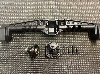
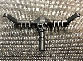
Open the package containing your new Currie F9 Portal Axle Housing, 3rd member Front: Capra 1.9 UTB. Install your existing differential and bearings into the new axle housing and reinstall the third member. Be sure to confirm proper ring/pinion orientation before tightening the third member.
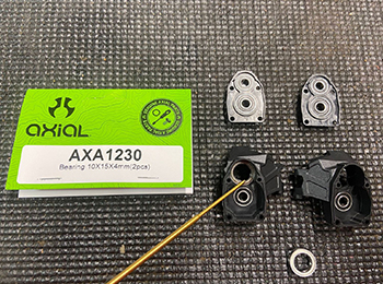
Step 5:
You will need to add a 5x11x4mm Bearing to each side of the housing before you attach the knuckles/portals. This is an easy thing to miss. Notice how this photo is taken after the housing is attached to the vehicle. I myself forgot….
Step 6:
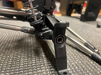
Open the package that contains the Currie F9 Portal Steering Knuckle Caps. Using M3x4x10mm Hex Button Head Shoulder Screw, fasten each knuckle to the axle. Note that technically the left is right, and the right is left (since we are building a front end that will be traveling/steering in reverse). Install all six bearings you removed from your portal housings in their proper locations in the knuckles and caps.
Step 7:
This is a bit tricky. You need to install new 10x15x4mm bearings in the location where my tool indicates in the photo. However, you need to slide the axles into the housing BEFORE installing the bearings. When you go to install the bearing, you may notice is a very snug/tight fit between the axle, bearing, and knuckle. Patience goes a long way here and I found it beneficial to “push” the bearing into place with a 10mm socket.
Step 8:
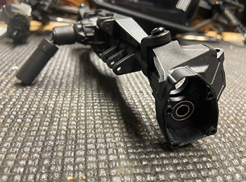
Install the portal gears and outdrive axles. Confirm that the pin behind the large portal gear hasn’t been misplaced or fallen out. You can now install the new portal covers, the axle spacers, and each hex.
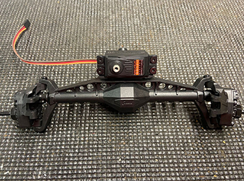
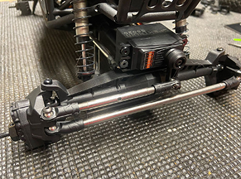
Step 9:
The axle housing is now ready for steering link and servo installation! Install your servo mount to the axle housing using two M3X8mm flat head screws. This is also a great time to mention that you can always reference the instruction manual that comes included with the Capra UTB. Remember, we are basically just building another front end, so all part numbers and diagrams should be accurately illustrated.
Step 10:
Install your servo to the bracket using four oversize 3x10mm head screws. Don’t waste brainpower trying to decide what direction to orient your servo as it does not matter which direction you choose. The servo actuation remains identical if the horn is on the left or right (I change the orientation of my links/servo to show this later in photos). Therefore, you absolutely MUST use a “Reversing Y-Harness” if you intend on using the stock three-channel receiver. If not, your Capra will only “crab” steer, regardless of geometry/orientation.
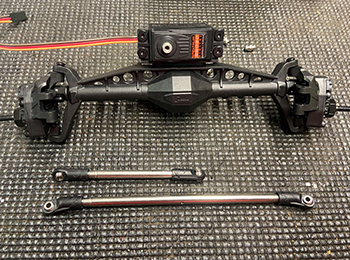
Step 11:
Build your steering links by installing rod ends. Unfortunately, at the time of writing this blog, the gray rod ends that come stock on the Capra were on backorder. I resorted to using the SCX10 style black rod ends instead. These come on a parts tree, but you will need to order two (2) of these trees unless you already have some ends lying around.
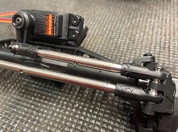
Step 12:
After centering your servo, install your servo horn/insert using an M3x10mm set screw. Attach the horn to the short steering link using one M3x12mm button head set screw. Stack the short steering link on top of the knuckle furthest from the servo horn, insert the long steering link beneath it, then use an M3x18mm button head screw to attach it. Finally, attached the other end of the steering link to the opposing knuckle using a M3x14mm button-head screw.
Step 13:
Install your new front… or rear... axle housing on your Capra. Remember to install your driveshaft before you attach all four links and each shock! Notice how I changed the orientation of my servo and links. I strictly did this to show demonstrate the capability. Again, there is no right/wrong way!
Step 14:
Problem Found: If you elect to run a full-size servo, it WILL interfere with the cage and/or receiver box before your suspension reaches full compression. Even though I strongly recommend running the same servo on both the front and rear axle (to maintain travel speed, torque, etc.) but I personally may make an exception and run a “shorty” style servo on the rear, such as the Spektrum S6230.
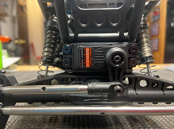
Step 15:
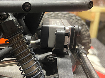
Here is a way to improve the issue from Step 14. I used a Dremel tool to cut and remove the cage portion that interfered with the servo. I removed the lower portion of this cage (where the red arrows indicate). Now the only true “bind” is the radio box itself! At this point, plug in your new rear-steering servo into AUX2 (you can use AUX1, but that’s where my DIG feature is).

Radio Setup
Step 16:
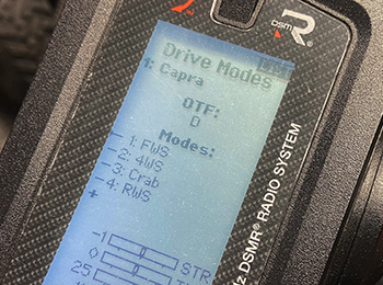
I will be using a Spektrum DX5 Pro radio to complete this process. However, these same steps should be applicable to both the DX5C and DX5 Rugged radios. After binding your model, enter the “Drive Mode” section of your transmitter. Assign the On-The-Fly (OTF) section to reflect whatever switch you intend on using to activate each steering mode. I use the “D” trimmer as it allows me to easily toggle between each steering mode.
Step 17:
Return to the function list, scroll up, and enter the mixing screen. You need to change your steering option to “active.”
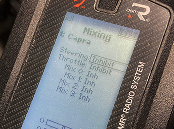
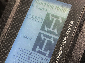
Step 18:
You also need to select the 4WS option here. Don’t get confused by the “2 Servo” selection. The “2 Servo” option is for vehicles using dual-servos on the front of a vehicle, common on 1/5th scale models.
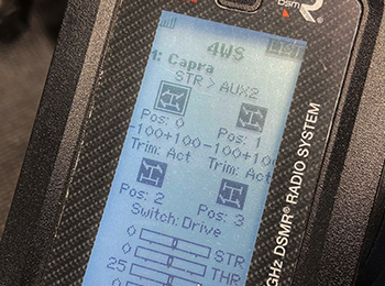
Step 19:
Finally, the last step is to change the “Switch” selection (pictured on the right) to the “Drive” option. This essentially is what talks to the drive modes we set up earlier. Once you “sync up” this functionality, your transmitter will display any/all steering options that are now available. The pictures, in theory, will mirror what you can expect your to do given that particular switch assignment. If it doesn’t you may need to reverse either the front or rear servo in the “reverse” menu (found back in the function list).
Step 20:
UPDATE: I swapped the rear-steer servo for a “shorty style” Spektrum 6230. Now I have complete/total clearance throughout the full suspension travel and in all angles of articulation (photo shown is full suspension compression). Note this servo is indeed much faster than the 6020 I have installed on the front, so I will likely swap that one out as well to better balance the steering speed.
Now, you should be able to check/adjust that each Drive Mode operates your steering as desired (see below). Remember, if you are using the stock RTR Capra electronics, you will NOT have the functionality shown below, only full-time 4WS. Also, check that the rear-end tracks straight when you operate the Capra in stock FWS mode. Trim this to correct any dog tracking that may occur should the servo deviate slightly from the from servo trim. At this point, you can close your receiver box and tidy-up any wiring that you disturbed when installing your new servo. You now have the ultimate 1/10 scale crawler! Your Capra benefits from the increased axle-height of portal axles, DIG functionality to help pivot/plant your vehicle in extreme off-road conditions, and four-wheel steering that enables your rig to turn on a dime OR crab your way through the most extreme conditions!
Additionally, be sure to watch our Horizon Insider Tech Talk video that further discusses and shows the incredibility ability this modification unlocks:
Parts List
- F9 Universal Axle Set(2): Capra 1.9 UTB (AXI232009)
- Currie F9 Portal Axle Housing, 3rd member Front: Capra 1.9 UTB (AXI232004)
- Steering Servo Arm & Inserts, 23T/25T: Capra 1.9 UTB (AXI234007)
- Hex Socket Button Head M3x25mm Black,(10) (AXIC0012)
- Currie F9 Portal Steering Knuckle Caps: Capra 1.9 UTB (AXI232006)
- M3x4x10mm Hex Button Head Shoulder Screw(6) (AXIC4403)
- M3 x 14mm Button Head Screw(10) (AXI235109)
- Susp Pivot Ball, Stainless Steel 7.5mm(10) (AXI234004)
- Steering Links, Stainless Steel: Capra 1.9 UTB (AXI234005)
- Hex Socket Oversize Head 3x10mm(10) (AXIC1009)
- Hex Socket Button Head M3x12mm Black(10) (AXIC0116)
- Bearing 10x15x4mm (AXIC0230)
- Bearing 5x11x4mm (AXIC0221)
- S6020 Standard Digital High Torque Metal Gear Surface Servo (SPMSS6020)
- SR515 DSMR 5-Channel Sport Receiver (SPMSR515)
- Rod End Set 4mm (AXIC3186) or HD Rod Ends M4(20) (AXI234006): Capra 1.9 UTB

: Capra 1.9 UTB")

")

")
")
")

")
")
")


